Nintendo Sheriff (prototype)
I've been asked to assist with the repair of a Nintendo Sheriff cocktail machine which has a PCB fault. As it's located overseas I won't be working on the machine itself and may not even work on the PCB set in person but will attempt to assist remotely at the very least. If necessary I may receive the original PCB set from the machine for repair and return to its owner.
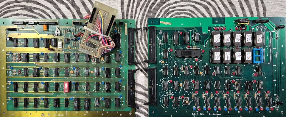
Already, there's an interesting twist to this story as the machine in question is apparently a prototype Sheriff game which was factory converted from a Space Fever black and white cocktail machine with modifications to the original Space Fever PCB set and Sheriff control panels fitted. Apart from the game software the main changes to the Space Fever hardware involve additional inputs for Sheriff's unique control panel layout.
The control panel features an 8 way joystick to move the Sheriff around the saloon / corral area of the screen and a rotary knob to control the Sheriff's direction of fire with push - trigger operation. It's been humorously compared to the knob on a gas cooker with its turn and push-to-ignite motion. Its nearest equivalent would be Bally Midway's Tron with rotational knob for firing direction or a dual stick shooter such as Robotron which uses a second 8 way joystick to control the direction of shooting.
Photo courtesy of owner
Interestingly the input expansion PCB which has been hand wired to the Space Fever I/O PCB bears the SEGA logo. It seems Sega were involved in the development and testing of the game in the North America region before it was licensed to Exidy and produced as Bandido for the local market. Sega / Gremlin did produce Nintendo's Space Firebird under licence so perhaps chose that game over Sheriff, leaving it up for grabs.
The name change from Sheriff to Bandido may have been due to a potential clash with Gottlieb's 1971 Sheriff, EM Pinball machine. The game waas also released in Japan by Taito as Western Gun 2, to follow their original 1975 game. The gameplay for Western Gun 2 is the same as Sheriff apart from the different musical tunes which play on coin up and game start.
Getting back to the issue at hand, the owner of the machine also has a working, production model TWG Sheriff PCB set which should be interchangeable apart from its RGBs colour video output. Adapting this PCB set to the black and white monitor in the machine is a possible solution, at least in the interim until the original PCBs are repaired. So I'll look into the differences between the two video formats to begin with.
I'm trying to help with an overseas repair of a Nintendo Sheriff cocktail table machine. It's a prototype which was factory converted using Space Fever black and white internals while the production version used a Sanyo colour monitor. My initial objective is to adapt a working, Sheriff colour PCB set to the original Space Fever black and white monitor.
That shouldn't be difficult but there will be some conversion required as neither version used 'standard' video or sync signal levels. Unlike more modern AV components which were designed to interconnect using standardised signals, early pre-JAMMA arcade machines were self contained systems so there was no perceived need for internal signals to be interchangeable with other devices.
The format which is commonly regarded as standard uses a positive video polarity, negative sync. That's not referring to a negative Voltage but the space between sync pulses is a higher Voltage level while the sync pulses are lower so the leading edge of the sync is a negative going transition. The black and white monitor used in Space Fever is really just a converted Television set and requires a positive video signal with separate, positive going sync.
Even the Sanyo colour monitors which were used in most Nintendo arcade titles of the era were evolved from TV sets without standard AV inputs and used a negative video polarity, negative sync. Fortunately, Sheriff and Space Fever were basically black and white games which had a colour overlay applied in the final stages so a positive going, black and white luminance signal is present within the circuit and can be used to drive the black and white monitor.
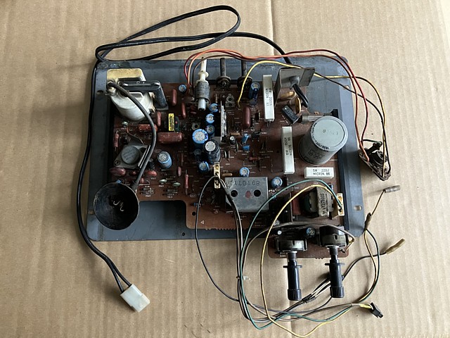
The sync will need to be inverted and in this case the level will also need to be boosted as the Space Fever B/W monitor seems to require a high level sync signal. Getting my Space Fever Black and White PCB set (which I repaired earlier) back on the bench to measure the actual video and sync outputs reveals the signals as below.
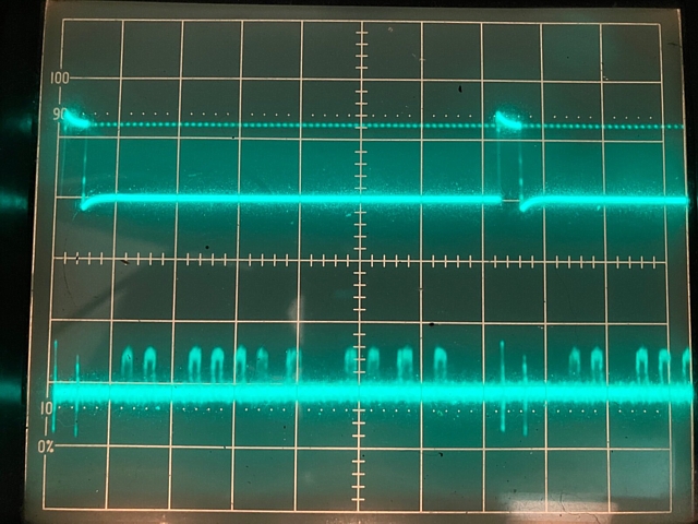
The lower trace, at 2 Volts per division with ground level set to the bottom line shows a positive video signal of about 1 Volt with around 4 Volts of DC bias. The upper trace at 10 Volts per division shows the positive going sync from ground level to a whopping +12 Volts. Compare that to standard AV sync level of just 0.3V, even TTL sync level used by many arcade games would only be 5 Volts.
I hadn't measured that before and was expecting the sync to be more like 5 Volts than 12. I haven't been able to find circuit diagrams for the black and white I/O PCB and the video output section is obviously different from the colour version so I'll trace the circuit from the logic section to the final video and sync outputs. Tracing circuits is time consuming and best done with a combination of visual inspection and multimeter to confirm connections.
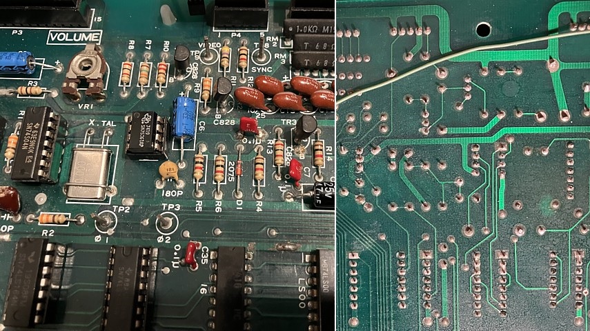
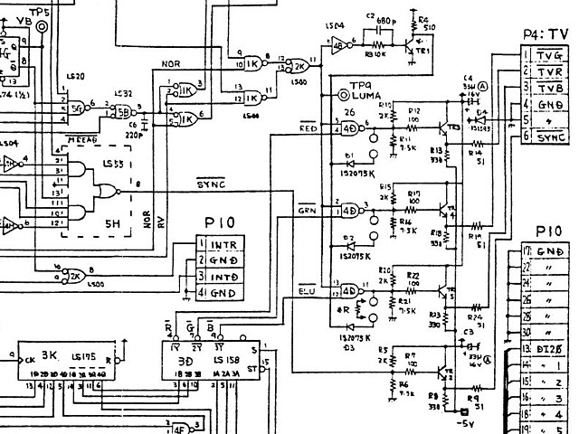
The photos above show the component locations and PCB tracks on both sides between the 7416 open collector inverter in position 2G and outputs on connector P4. And below is the circuit diagram which I gleaned from that section. In the photos, note that trimpot VR1 is incorrectly labelled as 'Volume' suggesting it may be an audio adjustment but in fact adjusts the bias and gain of the inverting Video stage TR1.
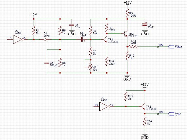
So the sync output is pretty straightforward, open collector inverter 2G, pin 12 with a pullup resistor from the +12V rail produces a 12V positive going pulse, buffered by common collector transistor TR3. It would seem that was specifically designed to suit the original Space Fever black and white monitor, which is the same as fitted to the Sheriff prototype machine.
The video circuit is more detailed and seems overly complex given the signal has no grey scale or shading at all, each pixel is either on or off. D1, R5 and R6 add some bias to the video (which is inverse at this point) followed by an inverting amplifier stage TR1 and output buffer TR2 to produce a positive video signal with some DC bias.
I'm guessing both signals have been carefully designed to match the video and sync signals which would have been present at the point where they are inserted into the monitor circuit. As that is a modified television chassis the video and sync seem to connect just after the TVs original IF stage which is still present on the PCB (inside the metal shield) but no longer required.
So to convert the video output from the later Sheriff colour PCB set to the black and white Space Fever monitor we can make up a little adapter and borrow some of the circuit details from the Space Fever I/O PCB output section.
The next issue is finding a circuit diagram for the Sheriff (TWG) PCB set. None seem to be readily available so, looking further I've found a copy of Exidy's Bandido manual with circuit diagrams. These seem to closely match the Nintendo Sheriff circuit and appear to have been originally drawn by Nintendo. One obvious alteration is the naming details at the bottom right corner of the diagrams have been blanked and overwritten by Exidy.
Looking at the video output section of the circuit diagram for Bandido, the design is very similar to the colour version of Space Fever with the black and white Luma signal from TP9 being fed to all 3 colour outputs via NAND gates in position 4D. At each screen position the individual colour outputs are either enabled or disabled by the colour overlay signals applied to the second input of the three NAND gates.
The default configuration for Bandido however was to use a black and white, Wells Gardner monitor with a physical colour film overlay applied to the face of the CRT rather than an electronically applied colour overlay in conjunction with a colour CRT. In this configuration all of the colour producing components on the I/O PCB were omitted including the quad NAND gate IC from position 4D.
In the Bandido manual an optional colour upgrade kit lists the omitted components which could be added and used with a colour monitor instead of the standard black and white unit. The circuit diagram also shows an additional driver circuit using transistor TR1 which can be configured to output a black and white signal via the RGB output section however this does not seem to be used on either the production Sheriff or Bandido machines.
Instead, the Bandido circuit diagram shows a hand drawn addition which combines the LUMA and /SYNC signals to produce composite video as required by the Wells Gardner black and white monitor, rather than separate sync. This is output via an additional 3 pin connector which is not present on the Sheriff PCB.
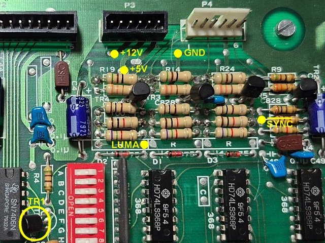
Interestingly, even though the production model Sheriff machines used a colour monitor the black and white driver transistor TR1 is still included on the Sheriff I/O PCB. In the photo below TR1 is present as well as the 3 diodes and spaces for the additional resistors to link the black and white signal to the video output buffers.
Although the existing circuit could be reconfigured to output black and white video that still wouldn't suit the original Space Fever monitor which requires a high level positive sync signal. So, instead of modifying the circuit I think it is easier to leave the colour output intact and add a little adapter with the necessary sync inverter, video output buffer and 5 pin connector to work with the existing cabling within the black and white machine.
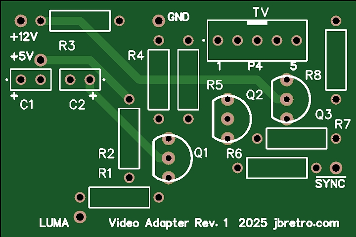
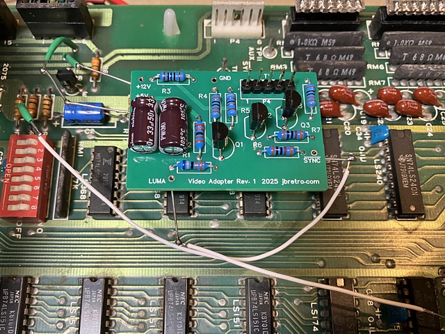
I've drawn up the small adapter PCB and positioned the connections to match the layout of the Sheriff PCB as shown above. The adaptor should be positioned just above the colour output section using the connecting wires as mounting points. Both colour and B/W outputs will be active so the PCB should be useable in either machine type.
I've made up a little adapter to allow a production model Nintendo Sheriff (TWG) colour PCB set to work in a prototype machine which was fitted with a Space Fever (TSF) black and white monitor. Apart from the obvious difference between a colour and B/W signal, each used different video and sync signal levels and polarity. Although the colour PCB set could have been modified to suit the B/W monitor, a custom adapter PCB seemed the better option.
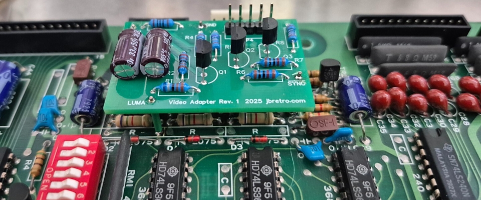
Here I've assembled the little add-on PCB which is designed to interface with the Sheriff PCB set, its connection points lining up exactly with the required signals from the TWG-IO PCB. I don't have that particular board set available for testing so I've temporarily connected the adapter to my Space Fever (colour) PCB set, using some wires to connect its inputs to the equivalent signals from the Space Fever (TSF-IO) PCB.
Having done that and with some minor adjustments to the resistor values the adapter output signals exactly match the measurements taken earlier from my Space Fever black and white PCB set. Viewing the B/W image on my test bench monitor the details look sharp and clear. That's a success so, sending the little adapter PCB off with simple installation instructions I'm confident the adapter will work well when installed in the actual machine.
- And here is the result (Photo courtesy of owner). The adapter and colour PCB set are reportedly working well in the B/W prototype machine with just some minor sound and monitor adjustment issues yet to be addressed.
Meanwhile I'll make up a second version of the adapter PCB to suit the Space Fever Colour PCB layout. That will allow the more common Space Fever colour PCB sets to be easily installed into earlier model black and white machines. I'll add one to my own colour I/O PCB which will make a good, working spare for my Space Fever black and white project machine.
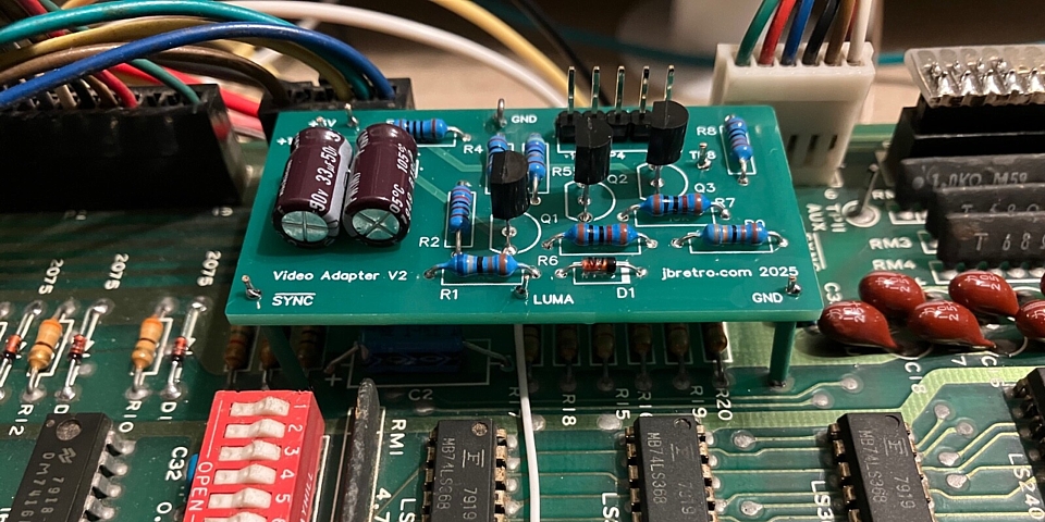
Here's the V2 adapter fitted to my Space Fever Colour I/O PCB, type 500813. The circuit is similar to the Sheriff version, in this case the Luminance signal is taken from a nearby via on the I/O board which traces back to TP9, LUMA and is connected by a short wire with a diode added to the adapter PCB.
The 6 pin RGBs colour video connector can be seen in the background, just behind the 5 pin B/W video +sync connector on the adapter PCB. Once installed both outputs remain active so the PCB set can now be used in either Colour or Black and White Space Fever machines without any need for modification to the machine wiring.
Web Resources (External Links) -
Space Fever (colour version) interconnection pinouts - CrazyKong.com
Sheriff TWG-1 operation manual, Nintendo - arcade-museum.com
Bandido, Exidy operator's manual (with circuit diagrams) - arcade-museum.com
All images and text on this website are Copyright.
Contact: jbtech at telstra dot com