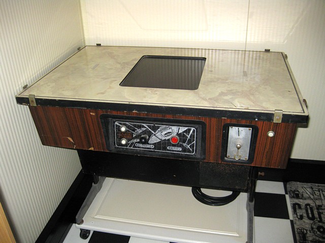
Logi Tec Space Invaders Colour TT
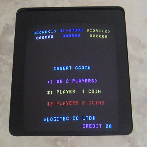
I recently bought this Japanese Space Invaders Colour TT (table top) because of its very original condition. It's not an original Taito machine, this one was made by LogiTec Corp in Japan but appears to retain all of its original components apart from the missing glass top, having survived more than 40 years without being modified or 'upgraded'.

Surprisingly this Space Invader 'clone' was apparently brought here by Taito Australia in 1980 and adapted for Australian mains supply and coinage, presumably after the 'Invader Boom' in Japan had peaked leaving a surplus of inexpensive near-new machines up for grabs.
According to the date code on many of the internal components, this machine was made in 1979.
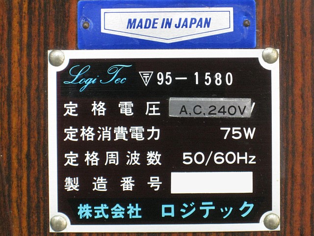
This one is not working at present, at first glance it appears to have power supply issues. In fact the linear (not switchmode) power supply PCB seems to have come adrift from its mounting slot on the lower rear panel and is laying on the (fortunately timber not metal) base of the cabinet, under the monitor.
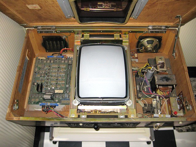
So the plan will be to test the monitor and game PCB separately and troubleshoot the power supply with a suitable 'dummy load' to prevent any further damage. The game PCB connections appear very similar to the Taito standard so I should be able to use my existing test lead for that, adapting if required.
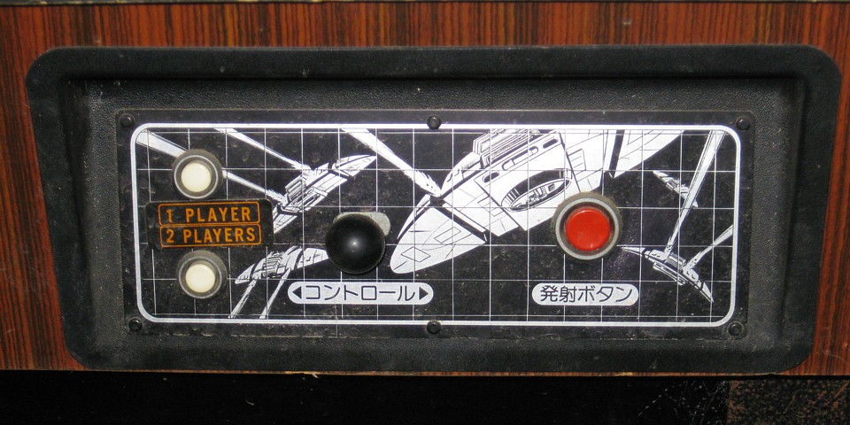
Checking the 36 way G and T connectors confirms they are pin compatible with my Taito SI Colour 3 board set. Using my existing test lead to fire the board up on the test bench I'm relieved to find all functions working correctly. That saves a lot of time as I already have a backlog of other PCBs needing repair and especially as there is no known documentation available for the LogiTec PCB...
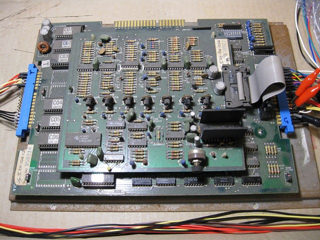
The Player 1 and 2 colour overlays appear to be identical to the Taito CV version but are achieved using different hardware. In fact the Logi Tec PCB set is more compact than the Taito colour original. The top PCB appears to be entirely devoted to the sounds which are nearly identical to the Taito version except the laser base firing sound seems to continue until the shot hits something or leaves the screen.
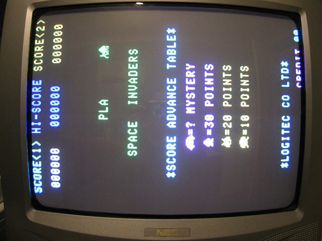
The next step is to test the machine's 14 inch Toei monitor. Using my monitor testing setup which supplies a transformer-isolated 110V AC to power the chassis as well as a 15kHz RGBS signal from a multi game PCB, the monitor can be run independantly while still mounted in the machine cabinet.
Another great relief to find the monitor is working well with no major issues as I also have a backlog of other monitor chassis to repair! I'll still need to temporarily remove the CRT with its mounting frame to improve access to the power supply PCB and wiring.
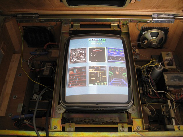
I've tested the Logitec Space Invaders game PCB and Toei 14" colour monitor and found both of these major sections of the machine are working, leaving the Power Supply as the likely cause of the machine's no-go problem.
Although I could just fit a new, modern switchmode power supply to get it working I'm hoping to keep it original, repairing any faults in the existing hardware. Next I've removed the CRT and its mounting frame to gain access to the 'bowels' of the machine.
Having done that I can remove the Power Supply Regulator PCB for closer inspection. This board must provide a regulated +5V, -5V, +12V and probably a slightly higher voltage (+18V or possibly just the unregulated +12V supply) to power the audio amplifier output stage on the game PCB.
This board also provides the power-on reset signal, preventing CPU startup until power supply rails are all present although it may just be a timer circuit, allowing the CPU to run after a nominal delay.
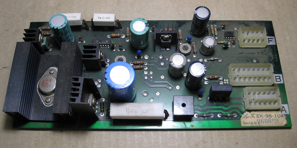
Apart from the obvious Electrolytic capacitors there are a few Tantalum caps, which have a habit of occasionally going 'dead short' for no apparent reason. When that happens, if the power supply has enough 'grunt' the result can be a bit of a flambe, as we can see here.
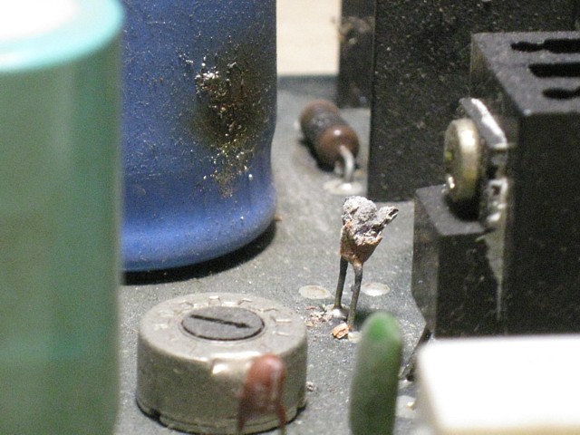
Comparing the remains of this one with others on the board I'm guessing this was a 4.7uF, 35V Tantalum. I could still read the '35V +' along the bottom but when touched it crumbled to ash.
Even after the fireworks, this cap still measures zero Ohms across and is probably the main issue stopping the power supply (and the game) from working.
Edit:- even if there's no visual indication of any damage the Tantalum capacitors are worth checking as a 'short circuit' one can put a supply into current limit.
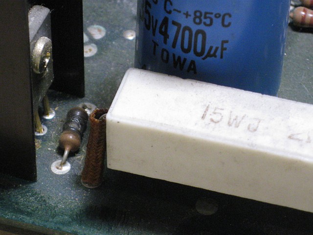
Probably as a result of the 'short circuit' Tantalum we also have a charred resistor, possibly part of a current sensing circuit on the affected voltage rail. Although blackened it has not burned out completely, removing it from the PCB to get an accurate measurement it reads 33 Ohms.
I'll trace out the circuit to try and confirm the correct value but that reading does seem believable and a 2W metal film resistor will fit in its place. The original may have been a 1W carbon resistor but the new metal film components have the benefit of being flameproof. Modern Tantalum capacitors also have a flameproof coating which probably comes in handy at times!
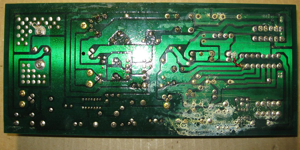
Looking at the back of the regulator PCB there's an unusual residue which I can't identify. There doesn't seem to be any evidence of previous repairs and the Electrolytic capacitors don't seem to have leaked onto the component side of the PCB but both of the nearby 1000uF 25V caps are a tiny bit bulged at the top - perhaps they have been emitting a gas or vapour.
I have some 1000uF 50V 105Deg. caps, with the correct lead spacing in stock so I'll replace those two straight away as well as the burned out Tantalum and clean that residue from the PCB. I'll order the other values and probably replace them as a matter of course, along with the blackened resistor to hopefully protect the game PCB from future harm.
But first I'll test the Power Supply in the machine, with no load to see if there are any other issues. Being sure to disconnect the AC supply from the monitor chassis and with the game PCB also removed I reinstall the regulator PCB and test the output voltages, finding them all present and correct.
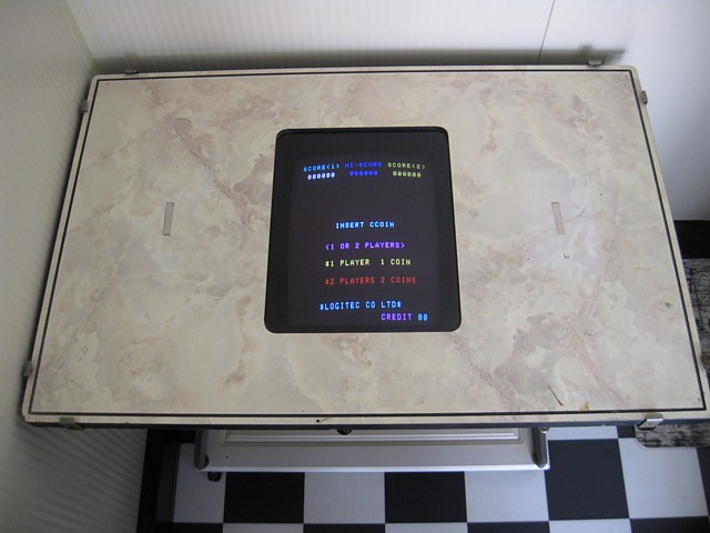
That gives me enough confidence to refit the CRT and game PCB in order to test the system as a whole. Upon powering up it's all good, the machine is working, sounds are fine, controls and screen flipping all functional.
When parts arrive I still need to complete the power supply repairs then I can move on to replacing the glass and touching up a few bumps and scrapes on the cabinet.
My power supply parts order is here, I've now replaced the damaged resistor and the rest of the electrolytic capacitors on the power supply regulator PCB for good measure. I've reassembled the machine and it's working well, the monitor is a bit jumpy at times and will need a routine overhaul soon but that's pretty much par for the course on these old units.
The sounds are all working but there might be a slight issue with the laser base firing sound - it's supposed to be a combination of a tone and a 'white noise' signal resulting in a sort of 'pssssshht' sound. The 'ssshhh' part is there but I'm not sure about the tone part. I'll have to look into that, using the Taito circuit as a guide.
The other thing I find slightly off-putting about the Logi Tec laser base sound is, unlike the Taito version which is just a short burst, it continues until the shot finishes and so is heard almost constantly during gameplay. I'll double check but if that's the way it's meant to be I'll leave it as such just to keep it original.
There's a bit of detective work involved with this Space Invader 'clone' as there's not a lot of information available online and some may be incorrect or just incomplete.
There's some suggestion that Logi Tec were somehow affiliated with Taito at some point and I've no idea if that's true but many of the components are so similar they appear to have come from the same parts bin, so to speak. On the other hand they could just be a blatant copy...
By contrast, the actual game PCB layout is completely different to the Taito original and a Logitec version with a simple colour overlay may even have preceded the Taito colour version.
I've not seen the Logitec hardware with the basic 'white, green and red' overlay, which mimics the cellophane strips applied to the original Black and White SI upright but that's the overlay which has been duplicated in MAME and applied to the 'invaders' as well as the 'invaderl' ROMsets as far as I know.
But in fact the 'invaderl' ROMset which must have been dumped from a LogiTec PCB similar to the one in my machine, already includes the colour information for the 8 colour overlay. EPROM 7 is the colour ROM for both Player 1 and Player 2 overlays (the colours are slightly different for each) whereas in the Taito 'sicv' ROMset a pair of bipolar PROMs provide the Player 1 and Player 2 overlays.
The clue was in the ROM listings all along, every other SI version which uses 1kByte (2708) ROMs does so with only 6 ICs and the address range from 1000 to 1400 Hex is unpopulated. Versions such as 'sicv' using 2kByte (2716) ROMs do include the address range from 1000 to 1400 Hex but that part of the relevant ROM is actually empty.
If we look at the contents of the C07 EPROM from the LogiTec PCB graphically using the program YY-CHR, we can see the contents are not program information but a simple pattern, being the bits to control the colours on sections of the screen:

With a bit of deciphering it appears that the data begins at bottom left of the game screen and continues in columns with 32 blocks from bottom to top and 28 columns from left to right. The upper 4 bit Nibble of each Byte refers to player 2 and the lower 4 bits are for Player 1. Bits 3 / 7 are always set and apparently unused while bits 0 / 4 are Red, bits 1 / 5 are Blue and bits 2 / 6 are Green.
As the 'invaderl' ROMset is already listed in MAME it should be possible (in some future release) to fully implement the colour overlay and show the colours as per the contents of the C07 ROMfile.
To Be Continued...
Web Resources (External Links) -
Space Invaders, Arcade Video game by Logitec(1978) - Arcade-History.com
All images and text on this website are Copyright.
Contact: jbtech at telstra dot com