Donkey Kong by Nintendo PCB #1
I've been asked to test a couple of Nintendo Donkey Kong Arcade PCB sets with a view to repairing any faults and confirming which of the Donkey Kong ROMsets are fitted, possibly changing to a preferred software revision. Both have been stored for some time but were reportedly running prior to that, one apparently had an issue with the positioning of some of the sprite details on screen.
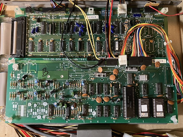
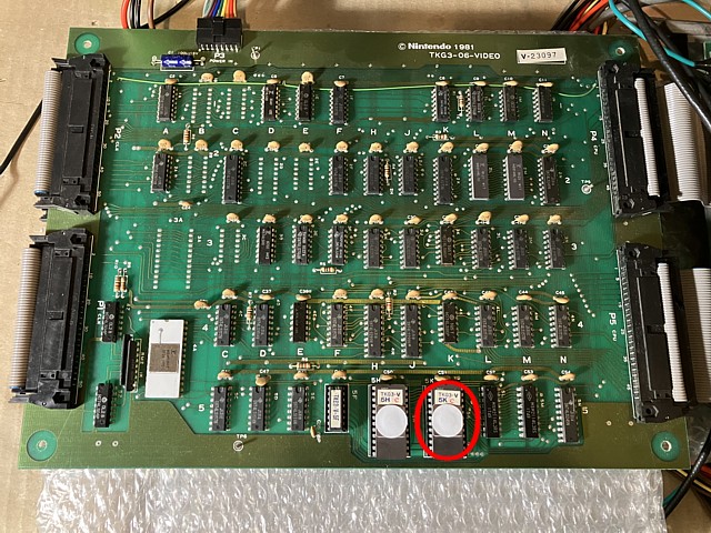
The one on the bench at the moment is destined for an original cocktail machine and is the TKG3 type, 4 board PCB set. I'm no expert on this particular hardware which has been extensively documented elsewhere so will refer to the existing knowledge base at times but hopefully add my own observations and interpretation of their workings as I progress.
The first step as always is to set the PCB up on the test bench with suitable connections, here I can once again adapt my Nintendo Space Fever test setup which has already been updated to include variations for Space Firebird and Space Demon PCB sets. Although some of the connections are compatible with Space Firebird pinouts I'll need to make an additional cable with 10 pin and 7 pin power connections for the CLK and Sound PCBs respectively.
Having done that I can make all the connections on the bench for power to the PCBs, Video out (via an RGB inverting amplifier to cope with Nintendo's 'negative' video polarity) and low level audio to my test bench RGB video monitor. To 'coin up' the game I can just use a small wire link to ground the input pin on the CPU board coin connector and for control I have an adapter lead to connect my Quickshot (Atari / C64 style) joystick to either the main or sub control input connector on the CPU PCB.
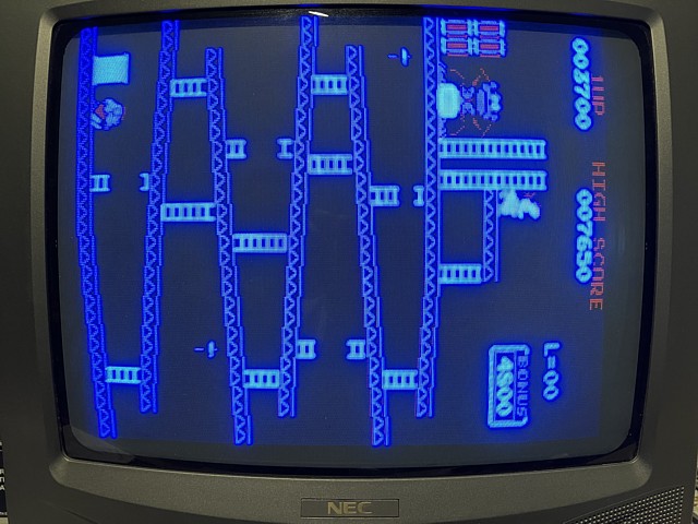
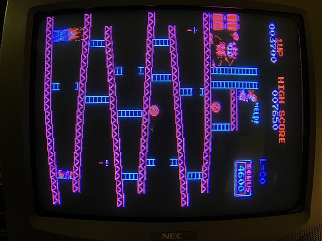
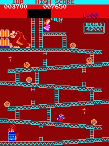
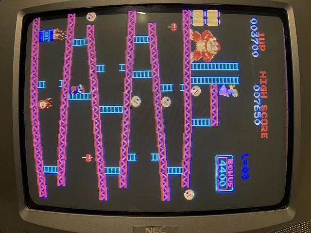
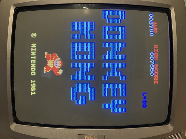
Powering on, there is a brief sound and the screen comes to life with a jumble of characters then the attract mode commences. Initially apparent are 3 issues, firstly the screen is predominantly blue with an elevated blue background level as well as washed out, overly intense blue characters on screen.
Additionally, some of the colours within the character sprites appear to be missing such as the middle of the Kong body, Mario face / skin tone details and part of the hammer graphic. After a little warm up some of the objects begin to appear glitchy and intermittent most noticeably the barrels and flame sprites.
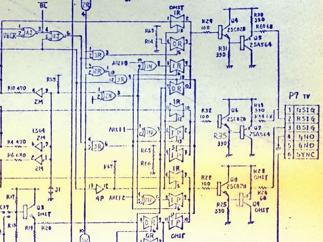
Looking into the most obvious symptom first, the increased blue levels appear to be the result of a deliberate design revision rather than a fault condition. Referring to the video output section of the circuit diagram the three colour channels appeared to be the same originally but the blue channel has a number of components which have been omitted or bypassed.
I haven't seen any other instance where a single colour channel has been altered to produce unequal signal levels but at this stage I'm guessing it was to give the intended Sanyo monitors a bit more adjustment range in the blue channel. In an arcade monitor the three colours are pretty independent, each with separate gain and lowlight adjustment so could cope with signals having unequal levels.
For my test bench TV monitor adjusting the colour balance would involve using the service menu to change factory settings so instead I'm temporarily adding a 330 Ohm series resistor to the 68 Ohm blue output resistor R24 just to balance up the 3 colour signal levels - close enough for the test bench, anyway.
That done, the colours do look better but some of the colour areas within the sprites are still missing or incorrect and some of the sprite details still intermittent. Checking the circuit diagram, graphics information arrives on the CPU PCB from the video PCB, is latched into 2 x 74LS174 ICs in positions 2G and 2H and output via a pair of 256 x 4bit palette PROMs which determine the final output colours.
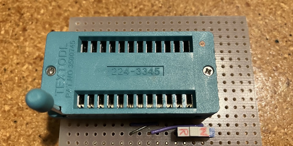
A problem with the colour palette could cause specific colours to be missing or incorrect so that would seem a good place to start. I don't have the means to program a replacement PROM but can read and verify the existing PROMS against known files using my old EPROM programmer with an adapter which I made to convert the PROM pinout to read as a 2716.
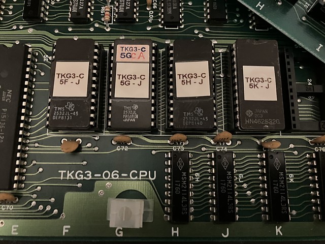
The adapter which I originally made for this purpose was on a small piece of veroboard, using a standard 16 pin IC socket for the PROM. I've recently made a PCB version with a ZIF socket which is preferable as the legs of the PROM ICs are notoriously fragile. Anyway, after reading the contents of the two palette PROMs in positions 2J and 2K on the CPU PCB both verify correctly against known files from the Donkey Kong ROMsets.
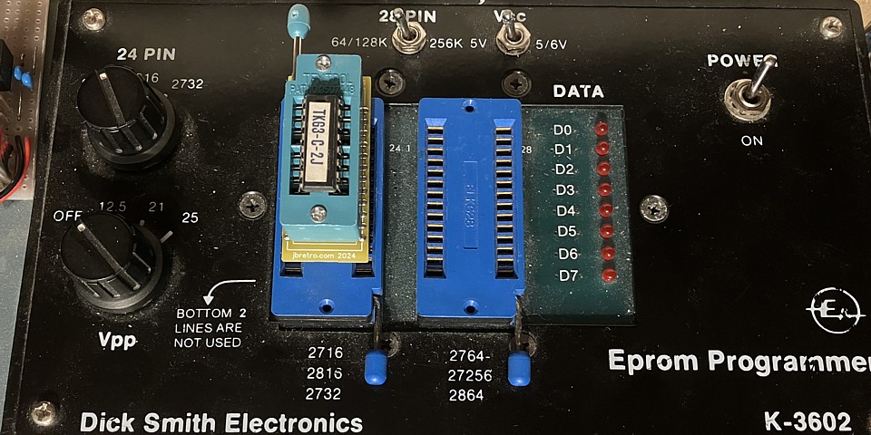
Before going too much further I'd also like to read and verify the program EPROMs on the CPU PCB and check the program and video RAM for errors. So the next hurdle will be reading the 4 x 2532 EPROMs on the CPU PCB which are not pin compatible with the more common 2732 IC.
Checking the data sheets for the 2532 EPROMs in use and the common 2732 type the majority of pins have the same functions and the programming sequence is similar for both, the only differences being the assignments of pins 18, 20 and 21. Those comprise the highest order address line A11, Vpp programming Voltage and the IC enable / programming pulse input (in different order for the 2 IC types).
So it should be possible to reprogram the 2532 EPROMs if required by making up another adapter to reorder those 3 signals. One other difference I noted between the 2532 and 2732 in read mode; the 2732 datasheet advises Vpp should be at logic Low i.e. 0Volts but Vpp on the 2532 should be held at +5V in read mode. So to use the same adapter to read and verify the 2532 EPROMs an additional switch will be required to select either read or programming mode.
To try it out I've made up the adapter, using veroboard again and successfully read the 4 CPU EPROMs which verify correctly as Donkey Kong, US set 1. I haven't tried programming any 2532 EPROMs as yet but that may be a task for later. The remaining EPROMs on the other PCBs within the set all appear to be more common 2716 types which my older EPROM programmer already supports.
I have a Nintendo Donkey Kong PCB set on the bench which runs with some minor graphics issues. So far I've checked the CPU program EPROMs as well as the palette PROM ICs and verified all are working, with data matching known ROMsets. I can verify the remaining EPROMs using my programmer to read them but as none of the RAM ICs are socketed there is no easy way to remove them and test them out of circuit.
To assist with a number of previous repairs I wrote some 'homebrew' test programs to run on various game PCBs, checking the RAM in circuit from the CPU's point of view. I've since ported the original programs to run on other game PCBs which employ similar hardware and think the program which I originally wrote to test some Exerion PCBs could be adapted to work on the Donkey Kong PCB set.
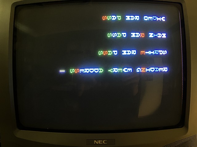
Both are Z80 based with separate RAM banks for background video / text and sprites as well as program RAM so with minor changes to the memory locations the program should run on the Donkey Kong Hardware. The video RAM is checked first which causes the jumble of characters on screen then once cleared the test results are placed into screen memory. For Exerion the text characters are Ascii based but the characters for Donkey Kong use different encoding so I've nicknamed it Donscii.
Unlike Ascii, codes 00 to 09 represent numeral characters 0 to 9, a blank space is represented by decimal 16 (10 hex) and upper case letters A to Z begin at code 11 hex. I haven't checked the remaining codes as other characters are not required for the test display, many seem to be segments of the background 'scenery' in the game screens. After assembling the adapted program and debugging in MAME it's ready to run on the actual Donkey Kong PCB set.
I don't have any spare 2532 EPROMs to load the test program onto so, comparing the pinout of the 2532 to the 2716 EPROM I realise as the test program is less than 2k Bytes a 2716 will work in place of the original 4k Byte 2532. The 2716 has 2 select inputs, /CE on pin 18 and /OE on pin 20 whereas the 2532 is selected when the PD/PGM pin 20 is low. Pin 18 on the 2532 is address input A11 which will also be low for the first 2k Bytes so the 2716 will work without any modification required.
And with the test program loaded onto a 2716 EPROM then placed in the boot ROM position 5F, powering on the tests run and each result is a pass. Even though that doesn't solve the missing colour problem it is good news as the memory components are becoming scarce and expensive. So the missing colour issues could be the result of a fault in the associated logic components or even possibly a bad interconnection between video and CPU PCBs etc.
I've been testing a Nintendo Donkey Kong PCB set on the bench which appears to be working apart from some incorrect colours and intermittent dropouts within the sprite graphics. So far I have verified the colour palette PROMs and CPU board EPROMs as well as running a RAM test on the main, video and sprite RAM banks with no errors found. The next step will be to rearrange the board set on the test bench to allow access to the video and clock PCBs and do some signal tracing within.
This TKG3 board set is evolved from earlier Nintendo games in particular Radarscope and being a 4 PCB stack can be difficult to access all areas for fault tracing. The CPU and sound PCBs are affixed to one side of a central mounting / shield plate with the video and clock PCBs on the opposite side and interconnection by ribbon cables as well as separate power connections to each PCB.
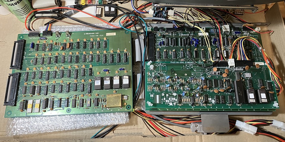
I've deliberately made my bench test cabling quite long to allow the PCBs to be removed from the mounting plate and spread out on the bench, by pivoting the video and clock PCBs through 180 degrees these can be positioned next to the CPU and sound PCBs. At this point, a short power interconnect cable between the video and clock PCBs prevents these two boards from being spread apart further.
To access the video PCB I could either make up a longer interconnect cable or just pivot the clock PCB a full 360 degrees so that it sits below the video PCB then reconnect the short link cable, also placing some non conductive bubble wrap between the two PCBs to prevent shorts. But first let's take a closer look at the clock PCB.
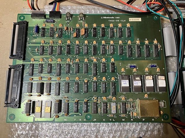
The clock PCB contains the main crystal oscillator and divider chains which provide the video sync and other timing signals, there is also a bank of 4 x 2716 EPROMs on board. These contain the 'gfx2' data while the pair of 'gfx1' EPROMs reside on the video PCB. Removing each EPROM in turn to check their contents, all verify correctly against the known Donkey Kong ROM file checksums.
An unusual feature of this PCB is the very high oscillator frequency 61.44 MHz and use of ECL logic components in the initial divider stages. I haven't come across this component type in other arcade PCBs to date and imagine by 1981 they would have already been largely obsolete apart from applications which demanded very fast response times.
There is also a pair of ECL RAM ICs on board, type 10422 each having only 256 x 4 bit capacity but extremely fast access time of 10 nanoseconds or less whereas the common 2114 static RAM used on the CPU PCB would have access times in the hundreds of nanoseconds. The ECL RAM does not appear on the CPU memory map so is not directly accessible by the CPU, it appears to be addressed using a pair of binary counters so I'm guessing it may be used for fast scrolling of sprites.
An added complication when using both ECL and TTL logic within a circuit is the need to interface between the two types, each having different logic levels. A number of 10124 and 10125 ICs perform this function, interfacing from TTL to ECL and vice versa. The ECL components also require a -5V power supply, their Vcc pins being at 0V, circuit ground level.
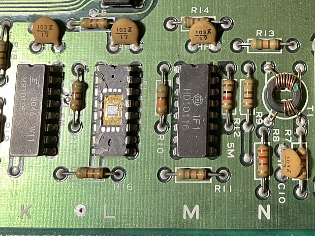
Looking more closely at the PCB I noticed one of the ceramic packaged, ECL ICs in position 5L was missing the top of its case. It had been covered with a label so had been that way for some time but I carefully removed the label to inspect the damage. Apart from the 'lid' being missing entirely there appeared to be some cracking of the adhesive cement which held the ceramic top as well as the IC legs in place.
Amazingly the IC was still working as none of the incredibly fine internal wires which join the wafer to the pins had broken. Nonetheless I think the best action is to replace the component as some old stocks of these ICs are still available from sellers overseas. This particular IC is a type 10136, high speed hexadecimal counter used in the initial clock frequency division.
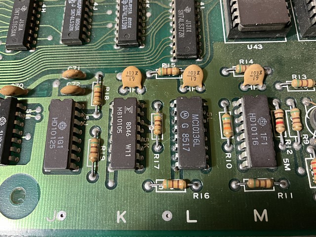
Getting back to the Donkey Kong PCB on the work bench, I've received the new old stock ECL counter IC to replace the one on the PCB which has a broken ceramic package. It was still working but with the internal IC wafer and fine connecting wires exposed the safest option is to replace it while this well obsolete component type can still be obtained.
The date code on the new part is from 1985 so just slightly newer than the original item and it also has a ceramic package. In this instance I'm soldering the replacement in position without adding a socket, mainly to retain the original appearance of this section of the clock PCB which employs a number of ECL logic components in ceramic packages. That done and powering the board set on again the game runs as before.
That's a relief as genuine, working replacements for obsolete ICs are becoming hard to source. Having rearranged the PCBs on the test bench, one of the initial problems with sprite characters having glitchy dropouts is no longer apparent so perhaps that was just caused by a bad contact in one of the interconnecting ribbon cables. I'll wait and see if that problem recurs and move on to the sprite colours or sections which are missing completely.
To trace that issue I'm not sure whether to begin with the clock or video PCB. Both have graphics EPROMs on board so I'm not sure from which PCB these sprite details originate. To learn more I'll do a little experiment with the Donkey Kong ROMset in MAME, substituting a 'blank' ROM file for each EPROM in turn to see what game functions are affected.
The same result could probably be achieved by removing the relevant EPROM from the actual PCB but testing the behaviour within MAME is safer, without any risk of incidental component damage.
Note: I've since found a page on the Braze Technologies web site which illustrates the exact same procedure (after I had already checked all of the Donkey Kong files in MAME for myself - I first used the same process to assist with fault tracing on an Exerion PCB a few years ago). I'll add a link below to the Donkey Kong Technical Info page from the Braze Technologies website.
Beginning with the CPU ROM files the results are much as expected with the game showing corrupted characters and going into a sort of reset loop at various points when each program ROM file is replaced. Substituting the ROM files for the clock PCB causes the sprite outlines to become blocky, this section appears to contain the sprite mask or outline information rather than the graphic details and colours.
When I substitute blank ROM files for the Video PCB EPROMs the background colours on screen are noticeably affected, it seems the character background colours are visible over the whole screen area instead of being keyed or masked to show only where characters are present. Interestingly, when video EPROM 'v_3pt.bin' is blanked the entire background of the ladder screen is a similar colour to the Kong body which could make it easier to trace the missing colour from the actual PCB.
That ROM file corresponds to the EPROM in video PCB position 5k so, powering the boards on with that particular EPROM removed from its socket the background is black rather than the expected dark reddy / brown colour. That will indeed make tracing the issue much easier, the problem now being apparent much of the time rather than just in one small portion of the overall video signal.
I've had a Donkey Kong (TKG3) board set on the bench for testing and a possible ROM revision change, for some time now and need to resolve what appears to be some missing colours or sprite details before moving on to the game software version. So far I've checked and verified major components EPROMs, RAM and colour palette PROMs are all working correctly.
Initially the problem seemed to relate only to the sprite colours but I now suspect the issue is more general as the details which were missing were a dark red colour while most of the other details on screen are brighter, more intense colours. To help trace the problem I've found a useful clue; by removing one EPROM (position 5k on the video PCB) the entire background of the game screen should be a similar dark red colour.
Running the actual PCBs on the bench, with that EPROM removed from its socket the background (as well as the Kong body colour) still appear black so using the oscilloscope to look at the 3 red output bits from the colour palette PROM in position 2J on the CPU PCB, there does seem to be some activity there which isn't apparent on the monitor screen.
That would seem to narrow the problem to the analog output section of the CPU PCB (after the colour bits are combined using resistors) or within my test bench setup - I've already encountered problems with what appear to be unequal signals from the three colour outputs of this PCB set.
Having a closer look at the circuit diagram of the RGB output section on the CPU PCB (as per the diagram near the beginning of this post) as well as my RGB inverting amplifier (which I've previously used successfully with other Nintendo PCBs Space Fever, Space Firebird, Space Demon) I'm beginning to realise the missing colours are not due to a PCB fault at all, rather an incompatibility between the Donkey Kong PCB and my existing test setup.
Specifically, the problem is that the inputs of my RGB inverting amplifier are all terminated with 75 Ohm resistors while the outputs of the Donkey Kong PCB are designed to drive a high impedance input. To further complicate matters a factory modification to the Blue channel output causes the Blue signal to behave differently to the Red and Green channels when faced with the unexpected 75 Ohm load resistance.
By lifting the 75 Ohm resistors from my inverting amplifier I should be able to proceed but I will try to illustrate why only low intensity colours are missing and why the colours behave differently. Also I should mention this problem would not occur if the original (Sanyo) arcade monitor was used for testing - which apparently has high impedance, inverted video inputs.
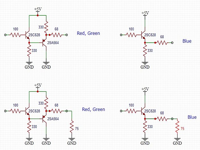
The three colour output sections on the CPU PCB are originally drawn as per the circuit in the diagram above, top left. For reasons still unclear Nintendo altered the circuit of the Blue channel only, to omit the final PNP output transistor, taking the output from the previous NPN transistor stage as per the circuit above, top right.. The notation 'OMIT" can be seen on several components in the original circuit diagram and I have verified these changes do apply to the components on the actual PCB.
At first glance the circuit, with an NPN and PNP transistor may seem like a complimentary output stage or even an inverting stage followed by output buffer but is actually just one non inverting buffer stage followed by another. Both transistors are configured as common collector (a.k.a. emitter follower) as they have a unity gain the signal at the emitter follows the input signal at the base of the transistor with just a slight DC shift due to the approx. 0.6 Volt Base-Emitter Voltage.
This configuration is generally used as a buffer amplifier as the circuit has no Voltage gain but employs the open loop current gain (Hfe) of the transistor to drive a load. This type of circuit is single ended, the transistor can only drive the output in one direction and relies on an emitter resistor to 'pull' the output in the opposite direction. In this case the emitter resistors are quite a high value, 330 Ohms so the circuit would not be expected to drive into a lower resistance load.
Having one buffer stage after another seems redundant (and to me looks like a bit of an afterthought) - the main difference being the final (PNP) stage may be better suited to the intended monitor which requires a video signal to be pulled towards ground rather than driven in the positive direction with a load resistance from input to ground.
This is where it all went wrong for my test bench setup, with a 'standard' 75 Ohm termination from each colour input to ground as seen in the lower two circuit drawings. On the left, the Red and Green channels would have been limited by the 330 Ohm emitter resistor's ability to pull the output signal in the positive direction given the unexpected load resistance.
This would have the result that signals with a more positive Voltage (= lower intensity as the video signal is inverse compared to a 'standard' video signal) would be clipped and become the same as black level. Meanwhile in the Blue channel with its altered configuration (bottom right) the transistor would be able to supply the additional current resulting in a full range signal with greater contrast than the Red or Green outputs.
So by disconnecting the 75 Ohm terminations from my test bench RGB inverting amplifier the missing details have reappeared and the colours look more correct overall. For future use I should have just enough room to add a 3 way DIP switch so the 75 Ohm terminations can be set on or off as required. Meanwhile after a brief test to check the game appears to be fully working I'll move on to the software version.
I have a Donkey Kong TKG3, 4 board PCB set on the bench for testing and a software revision change. Setting it up on the bench there were a couple of apparent issues with an overly intense blue image and missing red sprite colours. Both turned out to be caused by a mismatch between the Donkey Kong PCB set and my existing test bench setup, the PCBs to be tested were actually working and not the cause of the problem.
There were two other minor issues, the first was an intermittent glitchy dropout on the sprite characters which was most likely caused by a poor contact on one of the interconnecting ribbon cables. After rearranging the PCBs on the bench for testing and reconnecting the cabling that symptom has not recurred.
The only other problem found was an ECL counter IC on the Clock PCB which had a broken ceramic package, although still working the ICs internals were exposed and very fragile. Fortunately I was able to source a New Old Stock replacement for the damaged, obsolete component which would have been likely to fail at some point.
Moving on to the software revision, I have already read and verified all of the program, graphics and sound EPROMs and colour PROMs on the PCBs. All were confirmed working and match MAME set 'dkong' US set 1. Other commonly found ROMsets are 'dkongo' US set 2 and 'dkongj' Japan set 1. To identify the specific EPROM files which differ between each set I've cut and pasted the ROM file checksums so they can be compared side by side as below.
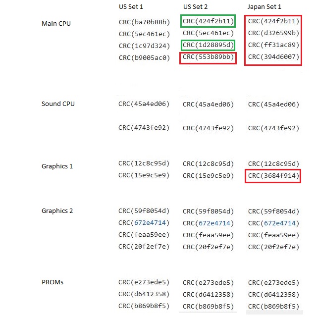
US set 2 is apparently an earlier release which was found to have an exploit in the first game screen where players could remain on the ladders indefinitely while the barrels rolled past, resulting in longer play times and corresponding loss in takings for the operators. Nintendo soon released updates for the initial versions so that some of the barrels would also fall down the ladders, putting an end to the 'ladder cheat'. Both US set 1 and Japan set 1 incorporate this significant update to the gameplay.
Along with the EPROMs fitted to the PCBs there were two additional 2532 EPROMs which I verified as belonging to US set 2, highlighted in green on the listing above. Presumably these would have been to change the existing software between US sets 1 and 2 however I've noted a third ROM file which differs between the two sets according to their checksums, highlighted in red. I'm not sure what the exact differences were or whether substituting just those 2 EPROMs would have worked.
In any case the set preferred for this particular Nintendo Cocktail machine project is Japan set 1 so I've highlighted the differences between the existing and preferred sets. All of the 2532 CPU EPROMs need to be erased and reprogrammed as well as one of the 2716 EPROMs on the video PCB. After erasing each of the 2532 EPROMs and using my programmer's 2732 setting along with the adaptor which I prepared earlier, all of the CPU EPROMs programmed and verified without errors.
The 2716 EPROM from the video PCB should have been more straightforward, with no adapter required but after erasing successfully and verified as blank the IC reprogrammed with a number of errors. Repeating the process gave a similar result, fortunately I did have a spare 2716 EPROM which programmed and verified correctly so after refitting the 5 reprogrammed EPROMs and powering on the game is up and running once again.
One notable difference which helps to identify the program version is the startup screen now attributes 'Nintendo' rather than 'Nintendo of America'. This would seem to be the more 'correct' detail for the Nintendo cocktail machine which the PCB set will be installed into.
The testing, minor repair and software revision update to the Donkey Kong PCB set has taken some extra time and troubleshooting. In the process I've upgraded my test setup, previously used for earlier Nintendo PCB repairs to also work with Donkey Kong as well as adapting my EPROM programmer to accommodate the 2532 EPROMs and porting one of my homebrew RAM testing programs to run on the Donkey Kong hardware.
With that complete I'll move on to the next Donkey Kong PCB which is the later TKG4, 2 PCB set with some reported sprite and sound issues. More to follow...
Web Resources (External Links) -
2732 Datasheet - ALLDATASHEET.COM
HN462532 Datasheet - ALLDATASHEET.COM
Donkey Kong Technical Info - Braze Technologies
Donkey Kong MAME driver - dkong.cpp - GitHub
Donkey Kong Memory Map - arcaderestoration.com
TTL/Bipolar PROM / RAM Reference Guide V2.f3 - retrotechnology.com
Pinout: Nintendo Radarscope/Donkey Kong/Donkey Kong Jr. - mikesarcade.com
All images and text on this website are Copyright.
Contact: jbtech at telstra dot com