DIY Arcade Christmas project
Here's a new scratch-build game project. It's intended to be a Christmas gift for two young family members so there is limited time available to complete from start to finish as well as a very limited budget. The intent is to produce something which has the overall appearance and feel of a 'real' arcade machine but is practical for home use and flexible enough to allow new games to be added or hardware and controls upgraded over time.
Although a reduced scale, 'Arcade 1up' style cabinet could be suitable in the short term I'm hoping to create a 'full sized' upright machine which the intended recipients can enjoy for as long as possible and not lose interest as they outgrow a pint sized 3/4 scale arcade 'toy'. Admittedly a riser base could be added to bring such a cabinet to full height but the proportions would never really replicate an actual arcade machine.
Having said that, one dimension which could be reduced without too much impact would be the overall depth to the back wall. Most arcade machines range from 750 to 900 mm depth (2 1/2 to 3 feet), partly to accommodate a bulky CRT monitor. Historically arcade machines evolved side by side with pinball so the extra depth was a desirable attribute. Electro mechanical as well as early video arcade machines sometimes included rear projection and half mirror optical effects which also demanded a large internal space.
For this application a flat screen LCD monitor is the preferred option for the sake of reliability (hopefully) and ease of replacement if required as well as power saving, less heat generated etc. So a reduced depth cabinet should be fine - I'm planning to use a 19 or 20 inch, non widescreen (4:3 aspect ratio) VGA monitor mounted with horizontal orientation. Vertical games from the golden age arcade era will still be playable, with a slightly reduced screen area.
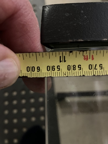
To compensate I'll mount the monitor in a more upright position to increase the apparent height of the image, this will also improve the viewing angle as most LCD monitors are best viewed square-on rather than from an oblique perspective. I've chosen a depth of just under 600 mm (or 2 feet) for the cabinet which will save greatly on materials cost as well as taking up less space in its intended location.
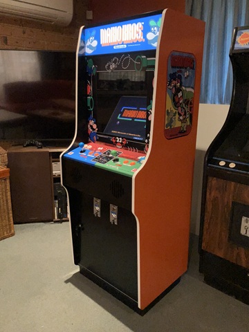
Having made those choices I'll pick a cabinet style, settling on a Mario theme which is a known favourite and remains relevant in the modern retro era. I've given some thought to various materials and finishes, to achieve a smooth coloured finish with the ability to further apply printed artwork (budget permitting) and minimal surface preparation I'll go with melamine faced particle board covered with self adhesive, coloured vinyl sheet.
Cabinet plans for exact reproductions of many arcade machines have been developed and shared online, in this case I'll adapt a DK style cabinet (link below) to reduce the overall depth while retaining the other dimensions and overall appearance. The most important detail to lock in is the exact shape and dimension of the side panels so I'll draw up, cut out and duplicate those to begin with, fitting the remaining panels to suit.
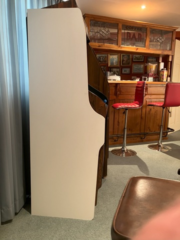
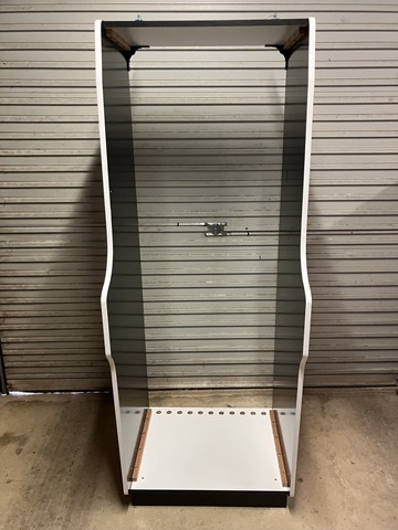
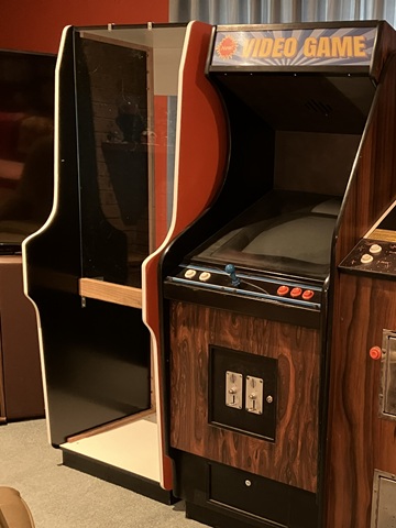
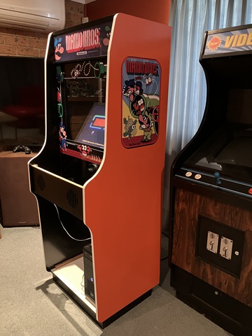
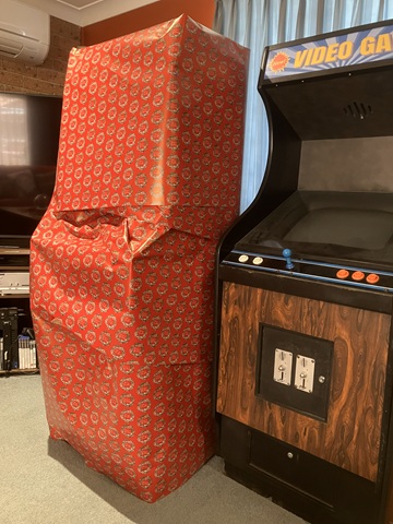
Here's the first panel cut, leaning against a pair of early '80s woodgrain machines. The height and control panel location will be similar once the new cabinet is assembled and mounted on a base plinth. In this elevation view the reduced depth of the side panel is easy to spot but will be less obvious from the players' perspective.
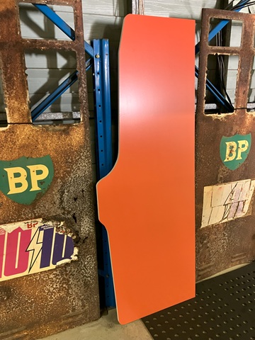
Both panels now cut and edged with white melamine (that may be upgraded to white T moulding depending on wear). This one will be the right side panel as viewed from the front so the outer face is covered with orange vinyl. The left panel is seen below, its inner face covered with black vinyl sheet. Only the front edge of the inward facing side will be visible from outside the cabinet but covering the entire inner side panels will help to darken the machine inside and hopefully minimise any light reflections.

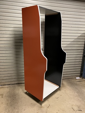
Here I've assembled the outer panels, using timber blocking strips screwed from the inside. I've covered the outer surface of the top panel with black vinyl but left the melamine finish of the bottom panel. It won't be seen from outside and will be more hard wearing as there will be a PC and other equipment installed in this part of the cabinet. As the machine will be for home use, to improve access I'll fit an opening door to the lower front as well as the usual removable back door panel.
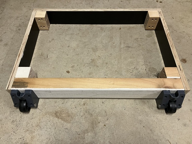
At the moment it's standing on a furniture dolly so the next step will be to assemble a base plinth with wheels so the machine can be tilted back and wheeled around on its own. The plinth is made with some offcuts of formply which has a hard wearing black finish. The rear part and corner blocks are treated pine so the base should be sturdy and have good resistance to moisture. The wheels are repurposed from a trolley.
Now that the outer cabinet stands on its own the rest of the panels and components can be made and fitted as we progress. In this view we can see a row of ventilation holes which I have drilled at the rear of the bottom panel, I'll add more at the top rear panel to allow warm air to escape by convection. There won't be any exposed wiring inside but I'll add some screen to the inside of the vents to keep bugs out.
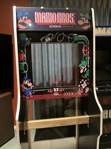
The next step is to add the front glass. I would have used acrylic (perspex) though that is quite expensive - as it happened I came across a small glass top desk which had been left for kerbside collection and the glass was the exact width to suit the cabinet without having to alter the intended dimensions. The length was not too critical, as the piece was longer than required the extra would disappear behind the control panel and not be seen.
The glass is toughened, with polished edges and 8mm thick so more than sufficient for the application. It is a little heavy so I have used a solid timber beam with a groove to support it, with some temporary brackets to retain it at the top until the angle strip is fitted later. The single piece of glass will be the main front bezel as well as the back for the marquee graphic which will be retained by a clear acrylic strip.
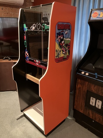
Having fitted the glass I have moved the otherwise empty cabinet into a clean area where the rest of the assembly can take place. I had ordered some printed artwork which just arrived so I've begun with the front bezel graphic and two sideart labels. As the cabinet depth is reduced the sideart graphics have been scaled down accordingly - they could have been a little larger but the limited budget was also a consideration here.
Next is the backlit marquee banner. I've added a metal strip to retain the graphic and acrylic sheet at the bottom (it's actually a length of flyscreen frame, the groove which would normally hold the rubber spline supports the marquee). At the top a black angle strip will eventually replace the temporary brackets. Inside, a pair of LED strips will illuminate the marquee graphic with a shelf added to enclose the marquee area preventing light spill onto the screen.
Now that the bezel graphic is in place I can mount the LCD monitor. I have made up a bracket with 100mm and 75mm Vesa mounting hole patterns which attaches to each side of the cabinet. Rather than mounting the monitor in a completely upright position I have placed it so that when viewed from a standing position (or seated on a tall stool) the viweing angle is correct.
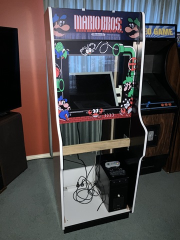
Here I'm also test fitting the PC - I wanted to accommodate a fully cased computer rather than an open frame to keep the internals neat and allow the entire computer to be easily swapped out if / when something goes wrong. The computer will have wires added for a cabinet mounted start /shutdown button and the 12V supply for the marquee lighting will be taken from a spare Molex drive connector within the PC.
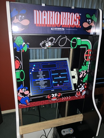
The PC is running MAME with Attract Mode as a frontend and an initial selection of games based on the 60 in 1 and 19 in 1 multi boards, with a few extras. From this photo angle the screen appears low but from a players perspective the screen area is centred within the bezel perimeter. I'll be adding a black mask screen surround to hide the empty space around and behind the LCD monitor.
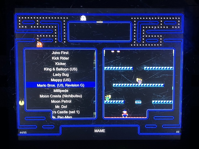
Here's the Attract Mode frontend display, just using the default layout 'theme'. There are a few light scuffs on the front bezel glass (which was repurposed from a glass top desk) and these show up in the photo when illuminated by the LCD screen but I'm not too worried about them - they don't seem so obvious during gameplay and somehow add an authentic 'feel' to the machine which is otherwise made almost entirely from new materials.
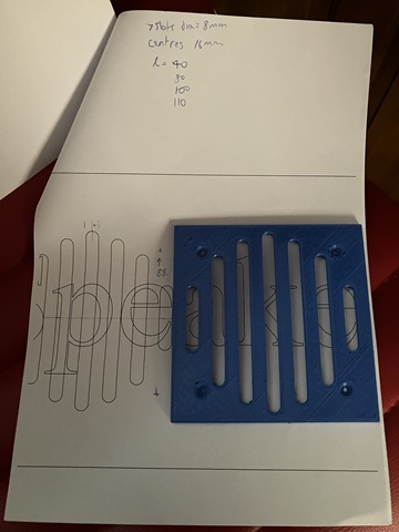
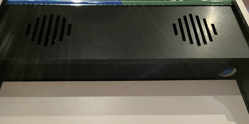
Before I can make and fit the control panel to the machine I need to add the front / speaker panel. This will support the control panel, I'll add a hinge and some latches so the control panel can be opened for ease of maintenance. The front panel is plain apart from a series of slots for the loudspeaker. Using a scale printout of the online plans I've drawn up and 3D printed a template of the speaker cutout with mounting holes to suit some speakers which I had to hand.
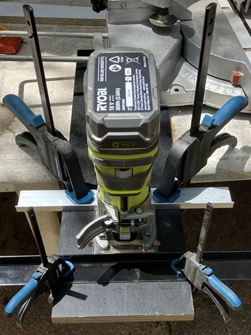
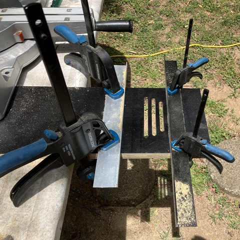
Although I initially thought the template might also serve as a router guide to flush cut the slots in the panel, some test cuts using that method weren't successful so I came up with a different approach. Here I'm using a small trim router with a pair of angle strips clamped to the panel to serve as guides. Using the leadscrew to gradually increase the depth of cut in approx. 1mm increments the small router with an 8mm straight bit produces a nice looking result.
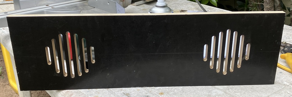
It's time consuming and for any quantity a CNC produced panel would be the obvious choice but for a one-off build it can be done. Having completed one set of seven slots I'll repeat the process as this panel will have two speakers fitted. The speakers themselves were another roadside pickup, a pair of rear - shelf car stereo speakers still in good working condition. And here's the slotted panel with both sides done - gotta be happy with that!
The front / speaker panel is made from formply which has a hard wearing black finish so there is no need to cover it with black vinyl. I may spray paint the inside edges of the slots black (from the rear to avoid overspray on the outer surface of the panel) as well as finishing the bottom edge with black melamine before mounting it to the machine with timber blocking strips, screwed from the inside.
The front / speaker panel adds structure to the machine and will support the control panel. I will use a piano hinge at the leading edge to accommodate some incline of the control panel and allow access for ease of maintenance.
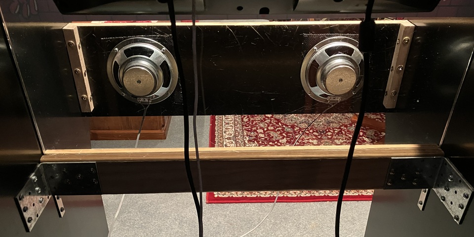
It turned out one of the car stereo speakers which I had recently picked up was faulty with a shorted voice coil. That may have been intermittent as I'm pretty sure they were both working when originally tested. Instead I'll use two new 5" (125mm) speakers which I already had, these ones are from Jaycar. I have been gathering parts for a new machine build for some time now so have an assortment of controls, speakers, coin mechs etc. on hand to select from.
With the speaker panel done I can test fit the control panel. The layout is based upon the Mario theme, with a second button added and 8 way joysticks which will allow a good selection of '80s era games. I haven't applied a control panel overlay as yet, the panel needs supports added with latches to lock it in place so countersunk screws can be used before the overlay is applied.
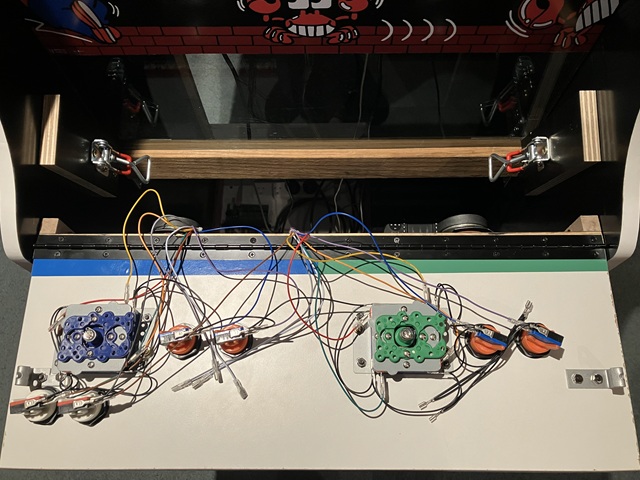
Supports and latches added, through hole bolts counterbored and artwork applied before refitting the control panel to its mounting hinge and connecting the prefabricated JAMMA wiring harness. I'll add some cable support once all of the internal components have been positioned.
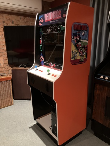
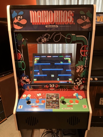
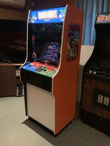
Looking good with the control panel closed and latched in place. The control panel overlay is clear laminated to hopefully withstand some wear. That's all of the printed artwork applied, I would call that a success.!
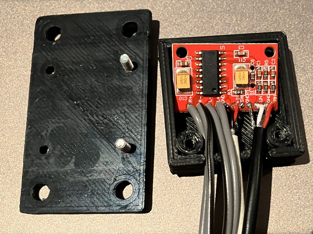
To drive the front panel speakers I need to add a small amplifier; this tiny postage stamp sized amplifier module is rated at 2 x 3W into 4 Ohms with a 5V DC supply so can be powered from a USB port on the computer. I have used these little amplifiers before to convert older, non-amplified PC speakers to USB powered. I had already designed and 3D printed a small enclosure to suit, this time I have added mounting flanges to the lid of the enclosure so it can be affixed within the machine.
After a few input settings have been adjusted within MAME the controls are all functional, games playing well and sound good. Most of the games which have 2 player alternating play use the player 1 controls for both but games which feature simultaneous 2 player operation make good use of the player 2 controls. Having the second joystick available for dual stick games such as Robotron, is also handy.
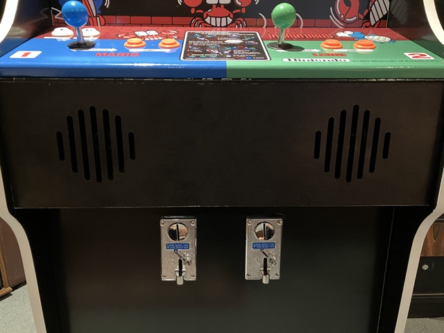
Test fitting the lower front door panel, this is mounted with a piano hinge and will close against a timber strip with a cam lock for access. Although for home use and not for commercial operation a pair of coin mechanisms will be added for an authentic look and feel, with the door also finished in black vinyl.
The DIY Arcade Christmas project has been progressing steadily but available time is obviously running short and I had hoped to complete the cabinet build by now. I'd like to use any remaining free time to run through the computer and MAME setup, sort out any issues with control settings as well as looking for suitable game additions which feature 2 player co-operative gameplay.
As the system is PC based it needs a mechanism to start up and shut down correctly rather than turning on and off at the mains. To achieve this I have added an extension of the PCs front panel switch and located this in a convenient spot just below the speaker panel. It is easy to reach but unlikely to be accidentally pressed during gameplay. To prevent the button from interfering with the top edge of the opening front door I have counter bored it flush with the panel.
The cabinet details which are yet to be completed include fitting the coin mechanisms to the front door as well as installing a removable coin tray inside the machine, adding latches to both front and back doors, finishing the front door with black vinyl sheet, adding a black mask surround to the LCD screen and fitting LED lighting behind the marquee with a partition to prevent light spill onto the screen. The LED lighting strips to be used are self adhesive and operate on 12V DC so can be powered from a spare Molex drive power connector within the PC.
Moving on to the screen mask this is intended to conceal the LCD monitor case and mounting frame while revealing just the screen area. It will be made from lightweight material and needs to be easily positioned or removed for cleaning / maintenance. To work out the exact dimensions and cutout position I'm making a template from some cardboard before cutting the actual mask from a thin sheet of plywood.
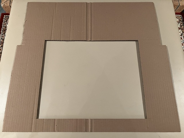
Beginning with a simple rectangle, I have found it necessary to notch the sides so the sheet can be manoeuvred into place via the slightly narrower rear door opening then marked the cut out to match the measured screen position. Transferring the final measurements to the plywood, I'm rounding the corners of the screen cutout to give an old-school appearance to the otherwise flat, rectangular LCD screen.
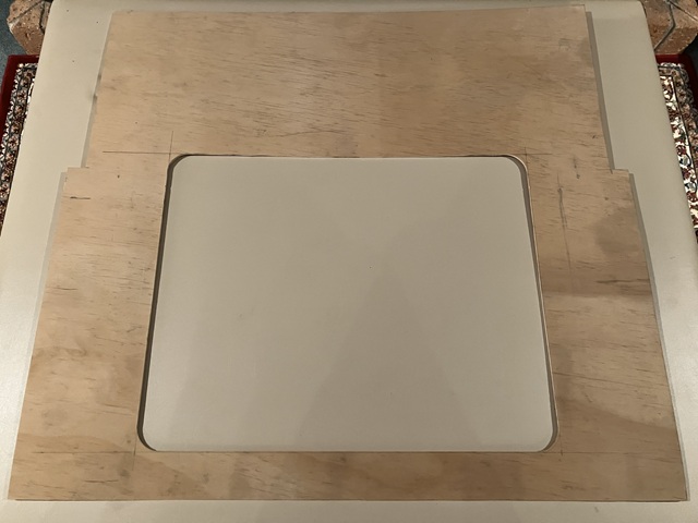
Having drawn the cutout area onto the plywood I used a drill with 44mm hole saw to make the rounded corners, cutting part way through from both sides to minimise chipping or splintering of the edge. Following that I have used a jigsaw to remove the majority of the cutout material, staying inside the required dimension. This allowed a final pass using the trim router with flush cutting bit, using a straight edge as a guide for each of the 4 sides for a nice, splinter free finish.
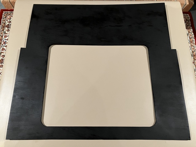
After a light sanding I'm spray painting the mask rather than vinyl wrapping to achieve a flat, non glossy finish and painting both sides to help seal the wood against moisture / humidity. This should prevent undue warping as well as allowing the mask to be turned over if required.
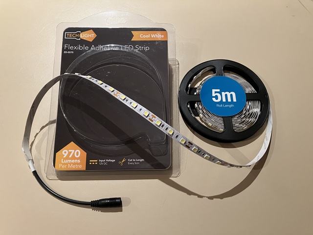
Next comes the marquee lighting. Instead of a fluorescent light I'll be using some self adhesive LED light strips which run from a 12VDC supply. The strips come as a 5m roll but can be cut into lengths (at 50mm or 2 inch increments) so I'll attach two strips each 550mm long to a white melamine covered particle board panel which is cut to the same height as the marquee graphic, 160mm. A second panel of 140mm depth will serve as a shelf / partition to enclose the 'light box' area and prevent light spill from the LED strips onto the monitor screen.
12V DC Power for the marquee lighting will come from the ATX power supply within the PC, using a spare Molex drive power connector on the power supply wiring loom. The current draw from the LED strips with total length of 1.1 metre is only about 1 Amp which translates to an additional power load of 12 Watts, still well within the total load rating of the ATX power supply fitted to this computer.
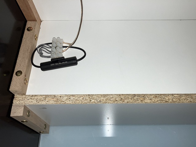
The other advantage of using the PC power supply is the marquee lighting will automatically power on or off as the computer is started / shut down. I have wired each LED strip to separate contacts on a small terminal block with a wire link so that either or both can be powered and added an in line fuse holder with 2 Amp fuse fitted to protect the power supply, just in case of any short circuit in the LED strips or associated wiring.
Powering the machine on for the first time with the Marquee lighting installed, the marquee banner graphic looks great but I'm surprised how bright the illumination is - it was intended to have a similar light output to a single fluorescent tube but is actually a bit dazzling when looking at the video screen. Lucky I did wire the two LED strips individually, disconnecting the wire link to power only 1 strip for a total of 6 Watts rather than 12 seems a more comfortable light level for the marquee illumination.
The second LED strip may not have been required after all, but will always be useable as a spare or may be needed if the marquee graphic is changed at some point.
The scratch built arcade cabinet is nearing completion, my current objective is to fit and connect a pair of roll down type coin mechanisms for an authentic play experience. Before launching into that however I need to tidy up and organise the cabinet's JAMMA wiring loom and USB interface. I'm mounting the interface in the lower rear corner of the side panel which leaves plenty of room for future expansion; the cabinet can easily be reconfigured to work with a JAMMA multi game PCB if desired (or as a back up in case of PC issues at some point).
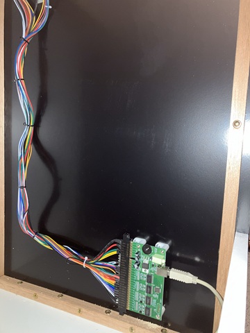
The interface itself appears to the connected PC as a pair of joysticks with multiple buttons for each so many of the controls are already correctly mapped to the MAME default inputs. There is an on board (mono) amplifier to drive the single loudspeaker connection which I'm not using in this instance, I've also separated the JAMMA power and RGB monitor connections on the wiring loom which are not used for a PC setup and bundled these together in case they are required in some future configuration.
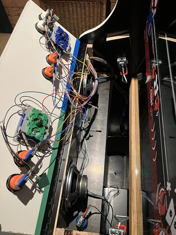
The player 1 / 2 and coin door wiring continue into the control panel area, skirting around the control panel latches. Player control cables are supported at the top corner of the speaker panel which allows the control panel to be hinged fully open with minimal strain on the wires. The coin door wiring snakes along the shelf below the speakers to emerge at the hinge side of the front / coin door.
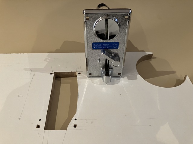
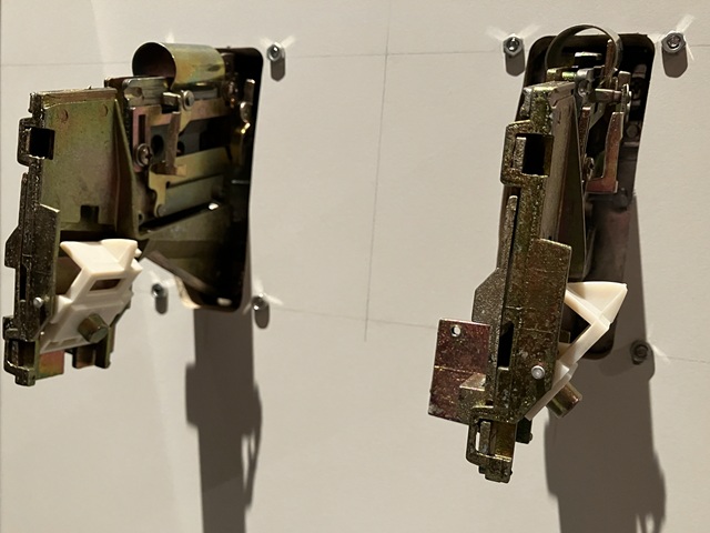
I have removed the front door to cut the openings for the coin mechs which were inexpensive clearance items. I wouldn't call them commercial quality but they are fine for this application, all metal construction and look the part. They came without micro switches so I have bought some which fit and should work fine. The mounting holes for roll down coin mechs are fairly standard but the cut out is quite irregular as the mechanisms are slightly angled with coin reject levers etc. needing clearance to operate so I 'm making a template using a scrap piece of board.
Having cut the openings in the template with a jigsaw, I've attached the template to the rear of the coin door using the mounting holes for alignment. I drilled / jigsawed most of the material from the cutout area before finishing with the trim router, then repeated the process for the second coin mechanism. The result is an identical pair of panel cut outs with nice rounded corners. I also used the trim router to make a slightly oval shaped mounting hole for the cam lock before covering the outer face of the door panel with black vinyl.
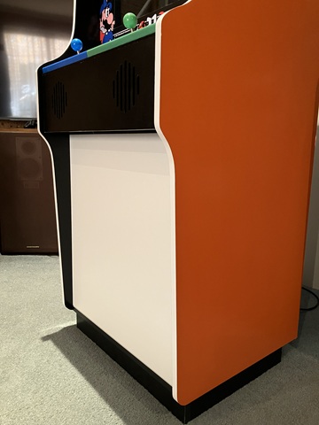
Looking good and that was the last remaining surface to be covered with vinyl sheet. I'm leaving the rear of the machine with its white melamine finish which is more hard wearing than black vinyl and will be facing the wall in its final position anyway.
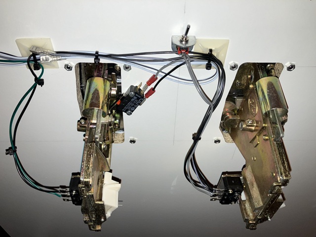
As an alternative to coin play I'm adding an inconspicuous credit switch which is actuated by pressing the RH coin reject lever. The added microswitch can be seen in the photo above along with the small toggle 'service' switch which enables or disables the credit switch function. In MAME there is no global free play option so a credit switch is the simplest solution. By the way, those self adhesive cable mounts in the photo are easy to use but do have a habit of coming adrift over time so I always add a countersunk screw to their centre hole before cable tying wires in place.
The machine is very near complete; I have fitted the cam lock to the opening front door and as the machine is for home use there is no need for a high security coin or cash box door. To catch any accepted coins I have found a small rectangular plastic 'bucket' repurposed from an old paper shredder. I'll just add some timber strips to ensure it is correctly positioned under the coin mechanisms, apart from that the last remaining task for the cabinet build is to add a keyed alike cam lock to the removable rear door.
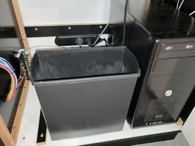
Here I have added some plywood strips to position the coin bucket under the coin mechanisms, another strip is attached to the bottom of the removable rear door which slots into place, the door is retained by a cam lock at the top. I've mounted a new power board to the fixed panel below the rear door with 1.8m (6 foot) lead which will reach the nearest power outlet without an extension cord.
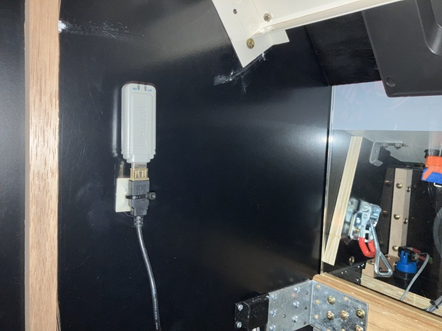
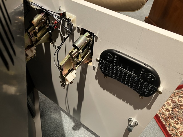
The system doesn't need an internet connection to operate but a WiFi connection is helpful when adding or configuring software so I have installed an older style USB Wifi network adaptor into the cabinet. Likewise no keyboard or mouse is required to operate within the MAME / Attract Mode setup but for system configuration a wireless mini keyboard with inbuilt trackpad is ideal. To stow the keyboard in a handy position, within the machine I'll add some retaining posts, just button headed screws with PVC sleeves as spacers.
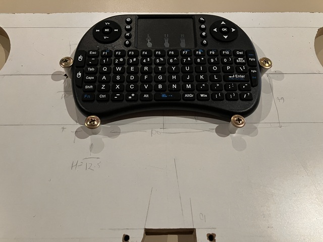
To work out the correct spacing for the screws I'm using the scrap board (above) before fitting to the inside of the front / coin door as per photo below. The keyboard and trackpad can be used to enter settings within Attract Mode and MAME or exit to the Windows 7 operating system if needed so it's best kept in a safe place for system administrators only. A small power switch on the top edge of the keyboard saves battery power when not in use.
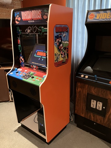
That pretty well completes the arcade machine scratch build, and just in time! Still to do is a quick run through of installed games, checking controls and coin settings etc. before the big day and then setting up in its final location.
It has been an interesting and very time consuming project with so many small details to consider but I think the result speaks for itself. I'm happy to pass it on and share the joy of retro arcade games.
Web Resources (External Links) -
Donkey Kong - Classic Arcade Cabinets
All images and text on this website are Copyright.
Contact: jbtech at telstra dot com